The closer you get to your subject, the less depth of field (DOF) you have. As you can imagine, when you photograph close-up or macro or micro subjects, you get progressively even less DOF.
In close-up—or closer—shots, even stopping down to your smallest aperture won’t give you enough DOF to make much of a difference. Besides, if you fully stop down your aperture, any small gain in DOF will likely be negated by diffraction, which softens the entire image.
Focus stacking blends multiple images with increasingly further focus points into a single image. This allows you to create an image with the specific DOF you want for your subject . You might not need everything in the foreground or background sharp, but you control what is or isn’t in focus by how many images (called slices) you use.
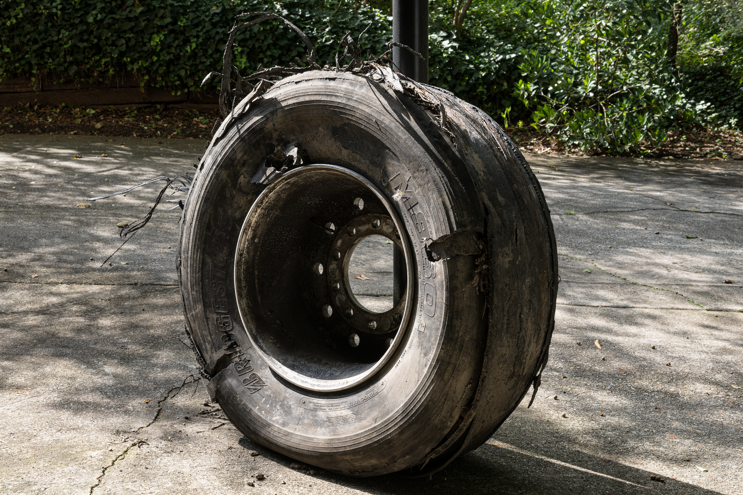
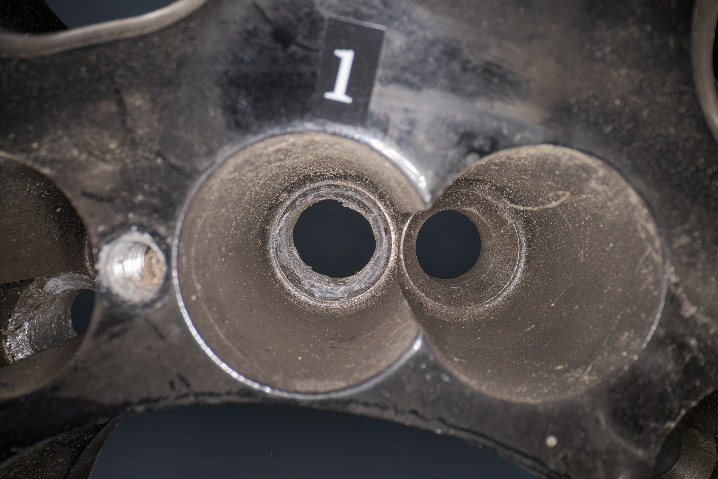
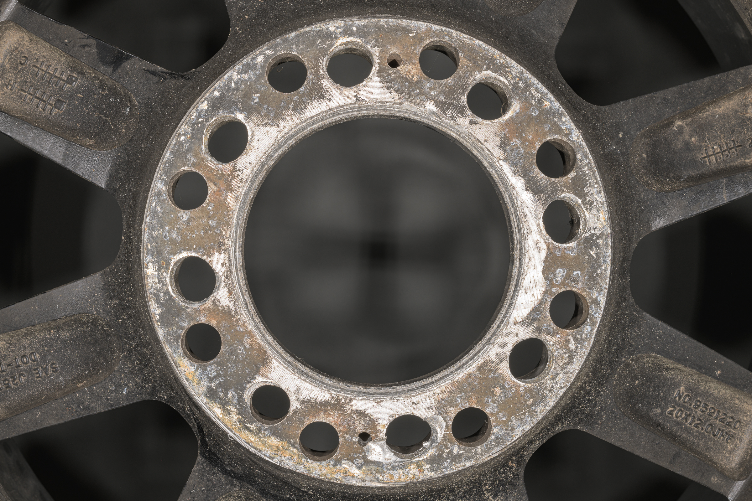
For this example, I wanted the entire broken lug stud in focus, but wasn’t concerned about the hub surrounding it. As shown below, even stopping down to f/16 didn’t give sufficient DOF to show the entire fracture surface. [Click on image to enlarge, then click on back arrow to return to this post.]

Notice how the focus quickly falls off toward the farther end of the broken lug stud fracture surface. Both the foreground and background of the hub are out of focus, but that’s okay since they’re not the subject of the photograph.
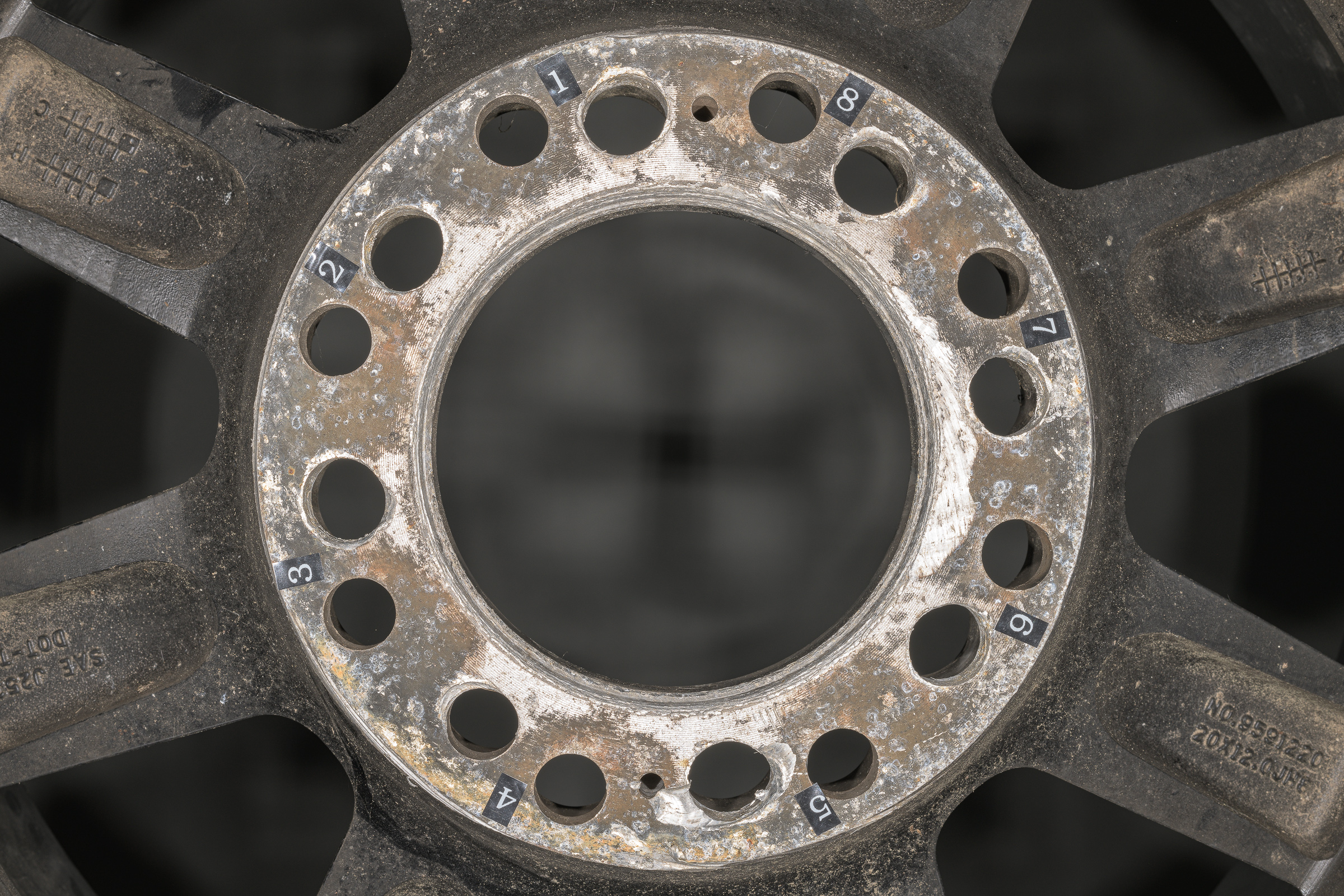
To get the entire lug stud to be in focus, I made nine separate photographs of the fracture surface with each one focused slightly further from the camera. [Click on image to enlarge, then click on back arrow to return to this post.]

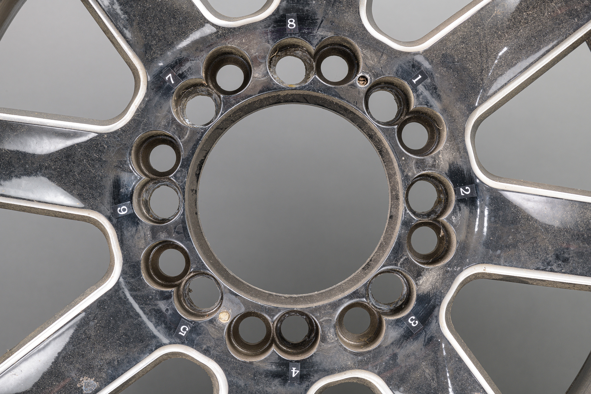
In Photoshop, I brought all of the raw frames (slices) into a single image as separate layers. I aligned the layers, then stacked them using Auto-Blend Layers. As shown below, using layer masks, this function blocked the out of focus areas on each slice. Only the sharpest parts of each layer, or slice, remained. [Click on image to enlarge, then click on back arrow to return to this post.]

I cropped the image back to its original size and saved it with all its layers as a PSB Photoshop Big) file. With ten 45 megapixel layers, the file was over 2 GB, which is larger than can be saved as a PSD (Photoshop Document) file. I then flattened the image, resized it, output sharpened it, and saved it as JPEG. Note: I still always keep the PSB file with the layers and layer masks to be able to show what I did, if asked.
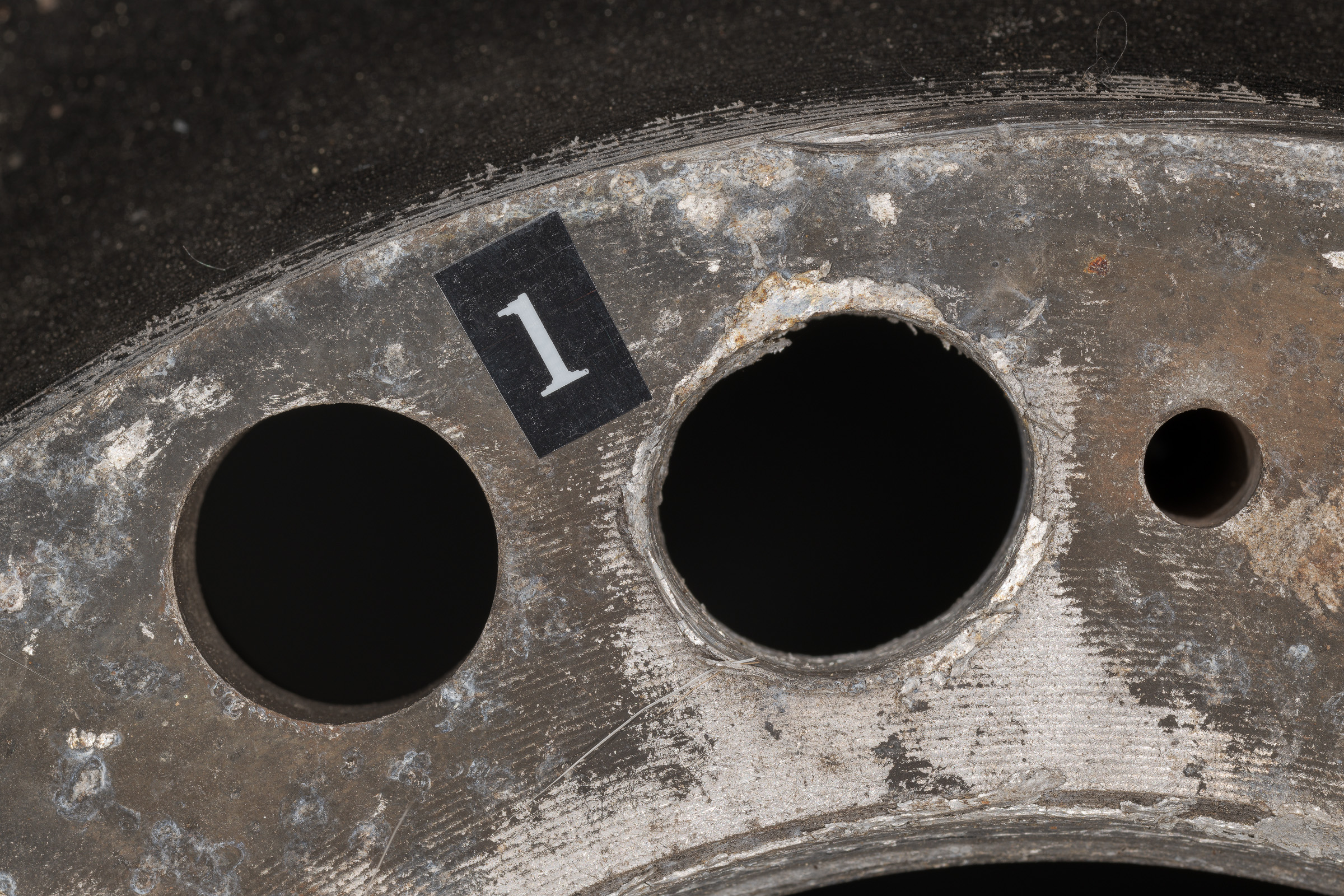
Below is the result of the focus stack blending of the nine layers shown above. [Click on image to enlarge, then click on back arrow to return to this post.]

Note how the entire face of the fracture surface is now in focus. Note: I used to also use Zerene Stacker and Helicon Focus for focus stacking—and both are excellent—but now I almost exclusively use Photoshop.
Takeaways:
-1- The closer your camera is to your subject, the less depth of field (DOF) you will have.
-2- Most forensic images require the entire subject to be in focus to show all its details.
-3- Even stopping your lens down to its minimum aperture won’t give you sufficient DOF, plus you risk losing detail from diffraction.
-4- Focus stacking requires a series of photographs (slices) be made with the focus increasingly distant from the camera. These slices are blended into a single image where only the sharpest elements of each slice will be kept by the software.
-5- Only combining images through focus stacking allows you to get sufficient DOF for many close-up, macro, and micro images.
-6- The closer the subject, the more slices (individual images) you need. For some micro images, more than 1,000 slices need to be blended through focus stacking.
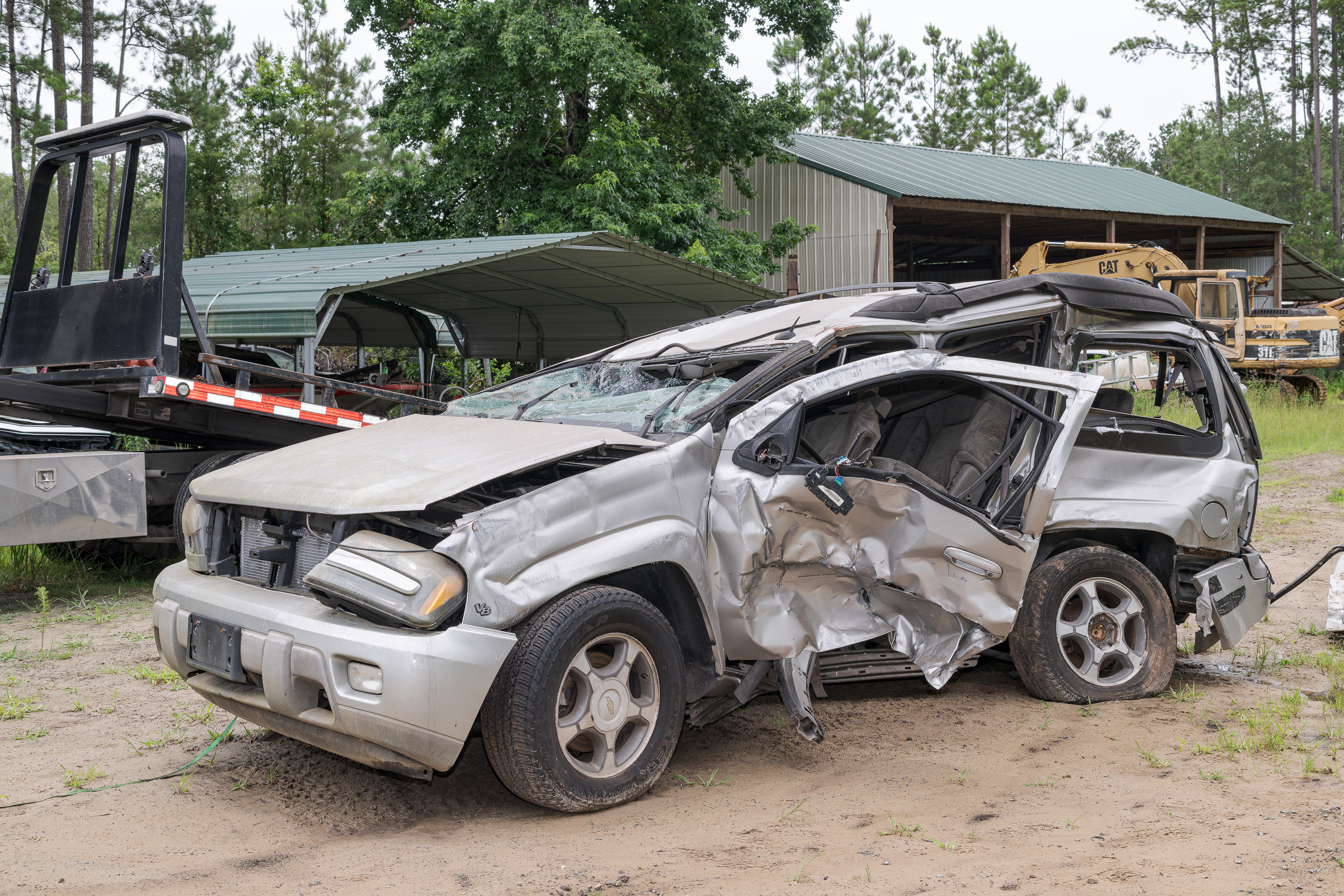
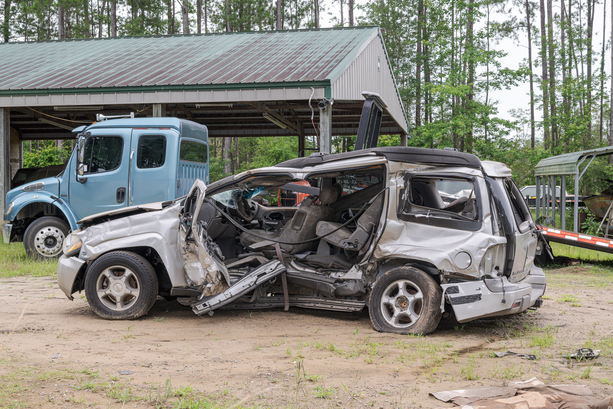
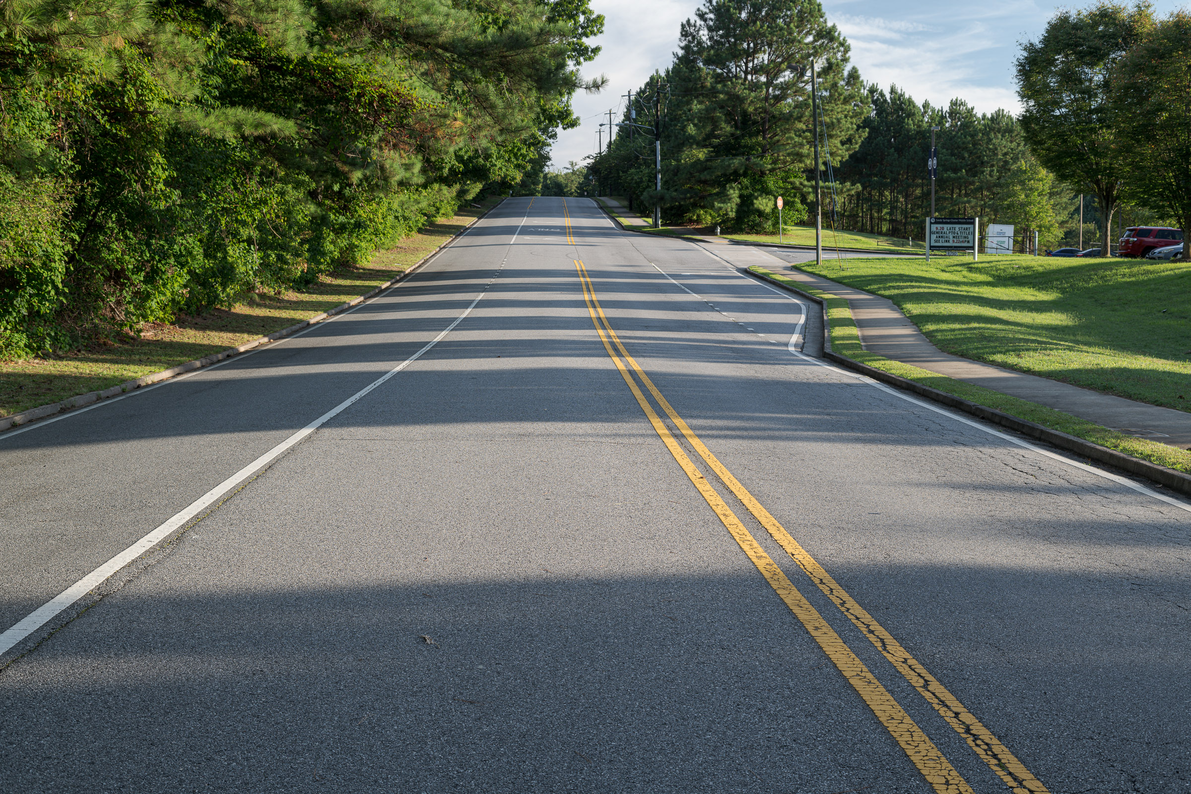
-7- Focus stacking can also be used for large subjects including landscapes, buildings, accident scenes, and vehicles. Those larger subjects require fewer slices—often only two or three.