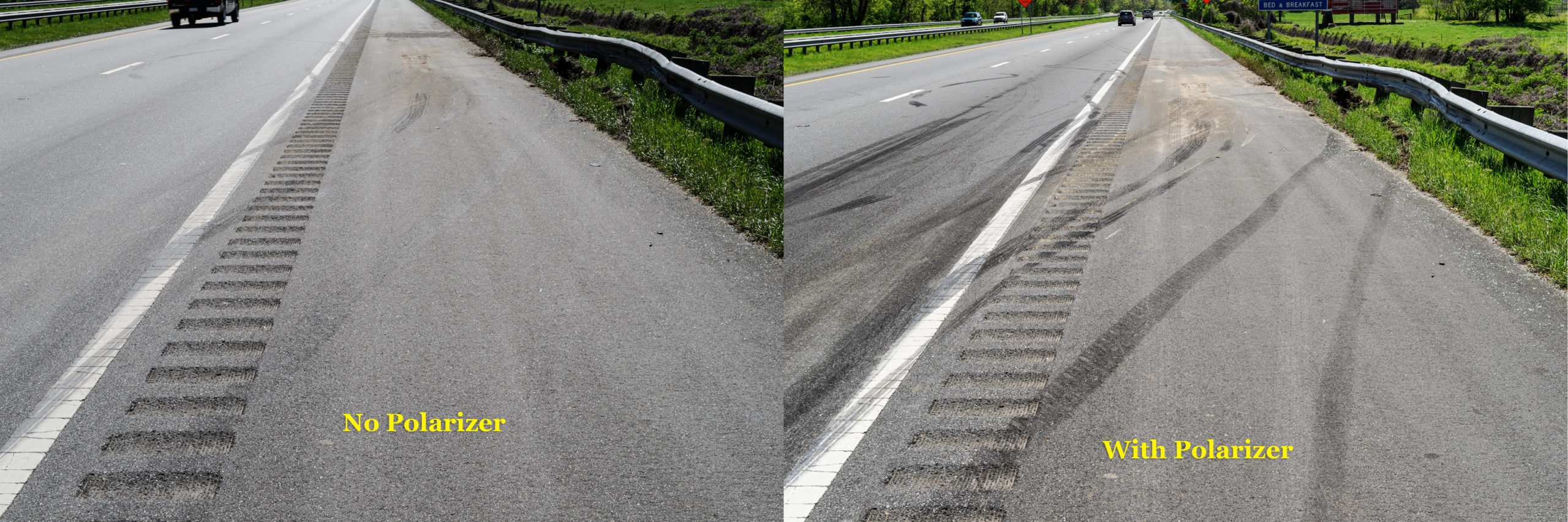
In my previous post, I showed the difference in photographing tire marks at a wreck site with and without a polarizer. In this post, I’ll show nine more comparison pairs illustrating other subjects we’ll cover in my SAE C1729 Photography for Accident Reconstruction, Product Liability, and Testing class: https://www.sae.org/learn/content/c1729/.
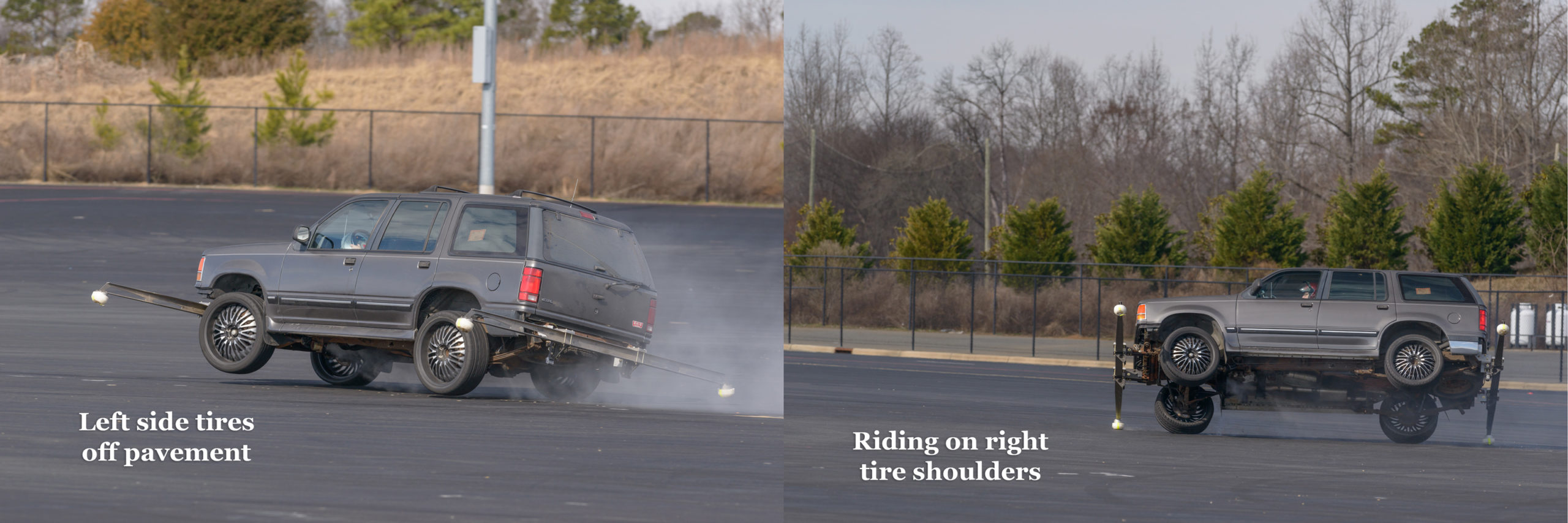
Tracking a Vehicle During Testing
Tracking by panning with Nikon D800E with 300 mm f/2.8 lens at f/6.3, 1/640 sec, ISO 400. [Click on image to enlarge, then click on back arrow to return to this post.]Using Fill Flash to Show Details in Shadows
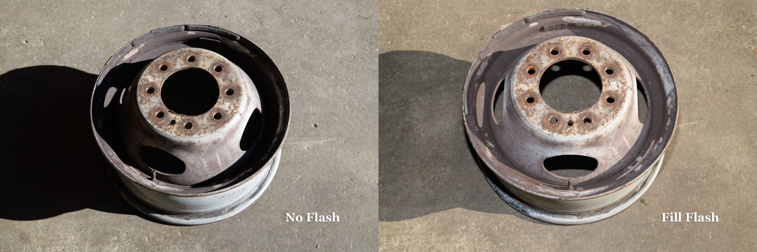
Both with Nikon D850 and ZEISS Milvus 50 mm f/2 macro lens. Left side: No flash at f/10, 1/60 sec, ISO 64. Right side: Fill flash at f/11, 1/80 sec, ISO 64. [Click on image to enlarge, then click on back arrow to return to this post.]Showing Depths of Abrasions and Damage Using Two Flashes vs Ambient
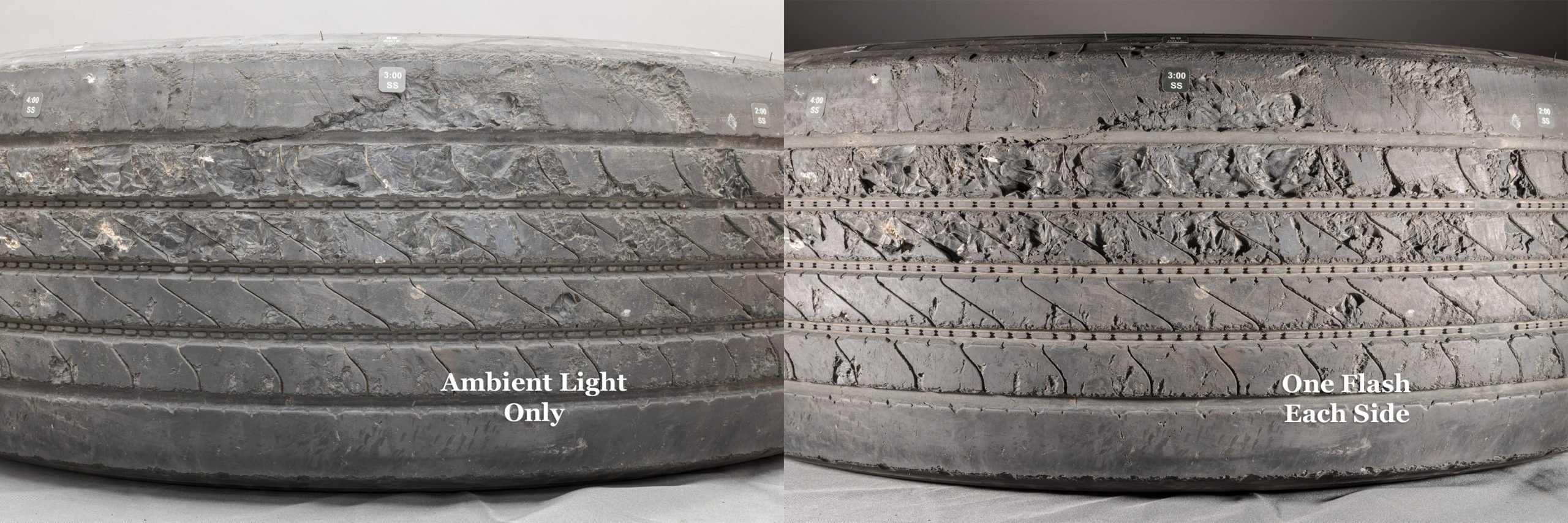
Left side: Ambient only; Right side: One Profoto B1x strobe on either side of tread. Both with Nikon D850 with ZEISS Milvus 50 mm f/2 macro lens at f/16, ISO 100, 4.0 sec left & 1/200 sec right. [Click on image to enlarge, then click on back arrow to return to this post.]Controlling Background Brightness while Keeping Flash the Same
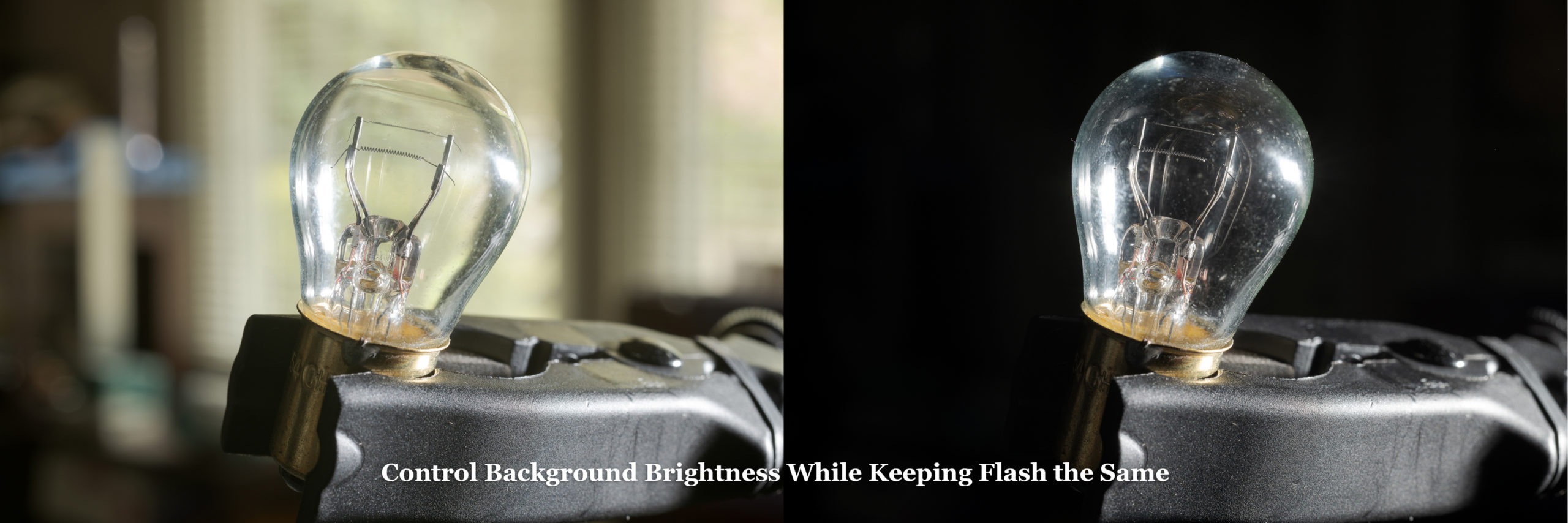
Both made with Nikon D850 and ZEISS Milvus 50 mm f/2 macro lens at f/14, ISO 64 with flash in hot shoe. Left side: 2.0 second exposure for bright background. Right side: 1/250 sec exposure for dark background. Background itself didn’t change. [Click on image to enlarge, then click on back arrow to return to this post.]Keeping Background Brightness the Same while Adding Fill Flash
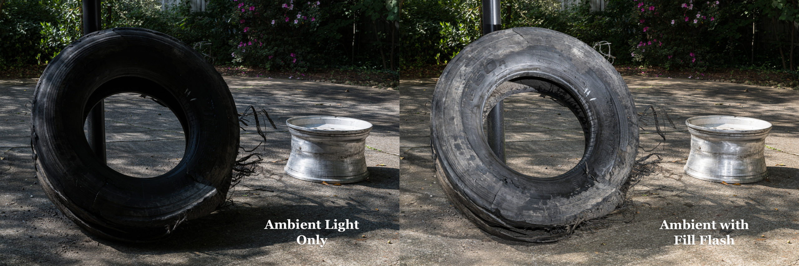
Left side: Ambient light only. Right side: Same ambient light with added fill flash. Both with Nikon Z 8 with ZEISS Milvus 50 mm f/2 macro lens at f/16, 1/25 sec, ISO 64. [Click on image to enlarge, then click on back arrow to return to this post.]Using Macro Flashes vs On-Camera Flash for Recessed Subjects
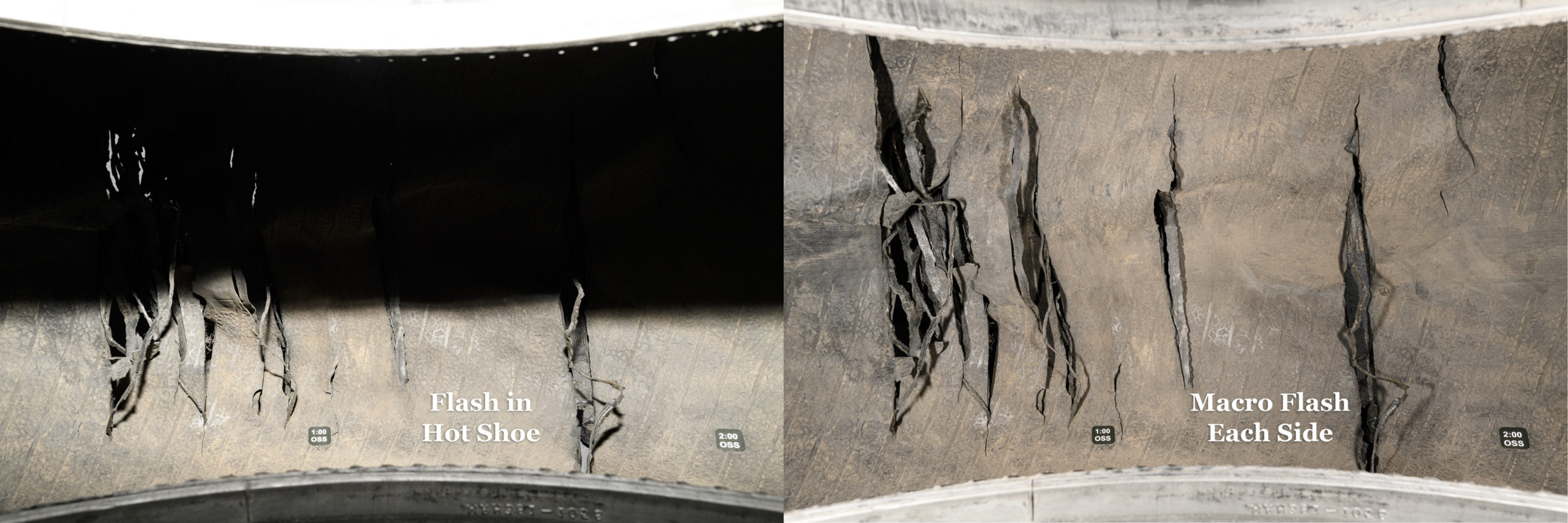
Left side: flash in hot shoe (Godox TT685IIN) with head tilted -7°; Right side: one small macro flash (Godox MF-12) on either side of lens—no light from hot shoe flash. Both with Nikon D850 with ZEISS Distagon 25 mm f/2 lens at f/16, 1/200 sec, ISO 64. [Click on image to enlarge, then click on back arrow to return to this post.]Unintended Deception from Camera Position, Even with Same Lens
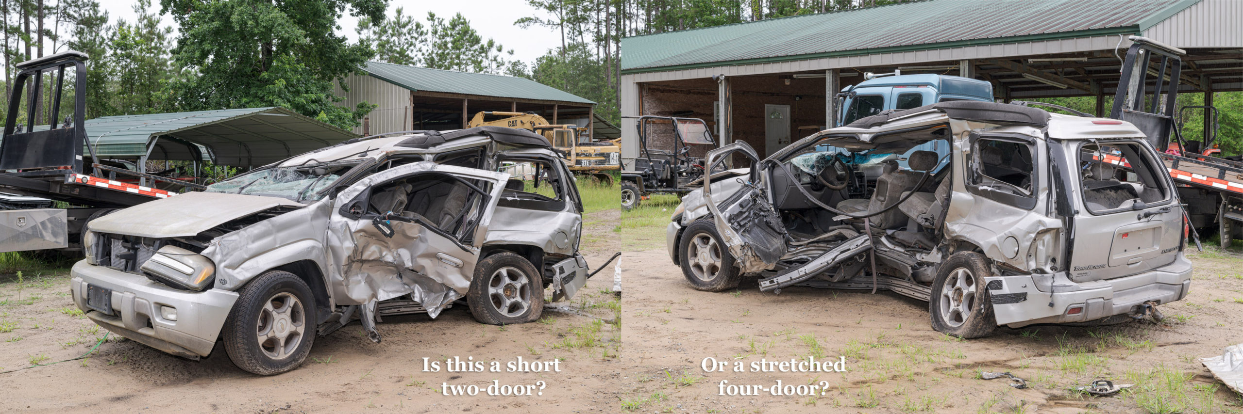
Both made with Nikon D850 with ZEISS Milvus 50 mm f/2 macro lens with fill flash. Left side: f/13, 1/40 sec, ISO 125. Right side: f/16, 1/30 sec, ISO 200. [Click on image to enlarge, then click on back arrow to return to this post.]Eliminating Glare on Plastic Evidence Bag Using Two Flashes
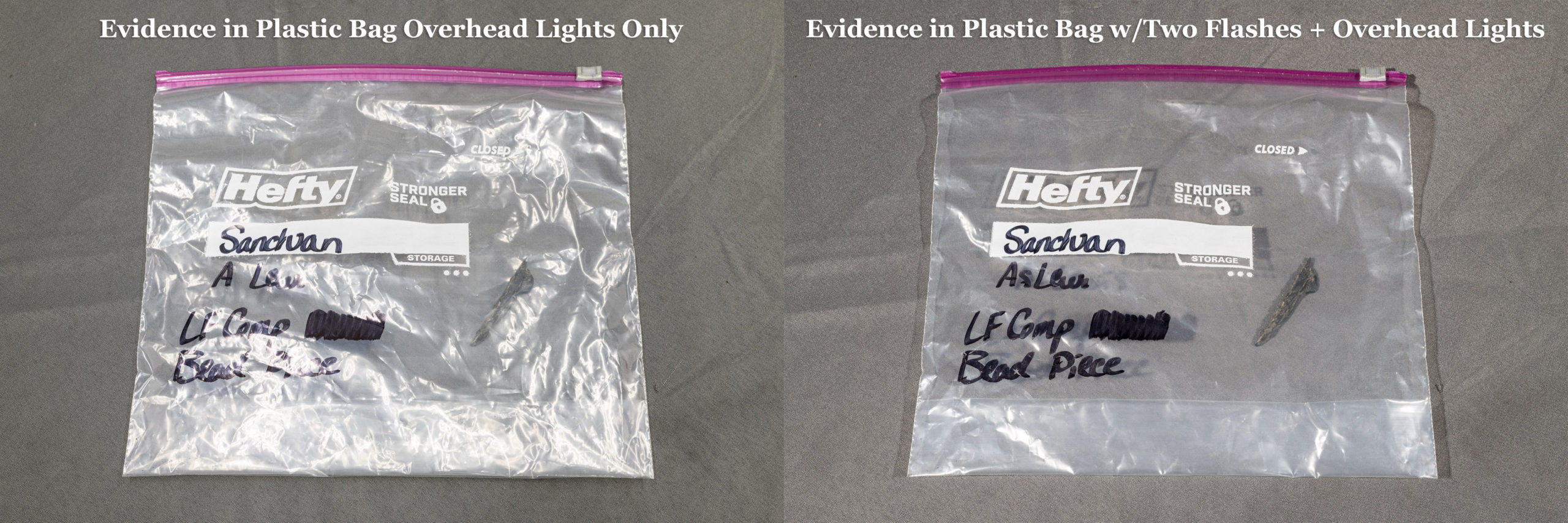
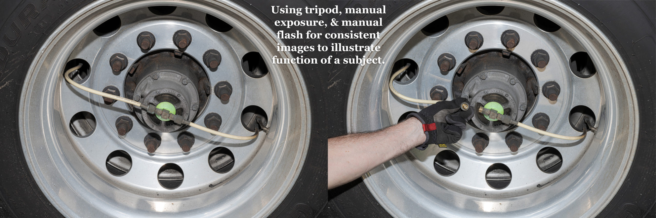
Both made with Nikon D850 with ZEISS Milvus 50 mm f/2 macro lens. Left side: Ambient only (f/16, 1.0 sec, ISO 16). Right side: Ambient with one flash at right and one at left (f/16, 1/200 sec, ISO 64). [Click on image to enlarge, then click on back arrow to return to this post.]Using Tripod, Manual Exposure, & Manual Flash to Ensure Consistent Images for Demonstrating Function of Subject
Using a tripod, manual exposure, and manual flash ensure consistency between images. Both made with Nikon D850 and ZEISS Milvus 50 mm f/2 macro lens at f/16, 1/40 sec, ISO 64 plus flash. [Click on image to enlarge, then click on back arrow to return to this post.]Some of you may have noticed that—except for the Explorer testing, the Trailblazer, and the onboard tire inflation system images—each pair of images had the same exact composition. Only the lighting changed. This was only possible by using a tripod. Tripod use will be another area of concentration and practice in the class. Hopefully, you’ll learn to love using your tripod like I love using mine.
I’ll post another set of photograph pairs later to illustrate additional areas we’ll cover in the class.
In the meantime, please don’t hesitate to contact me by e-mail or phone if you have any questions or would like more information. I look forward to seeing you in Reston, VA, in December. Again, here is the link for the class: https://www.sae.org/learn/content/c1729/.
Both 1/80 sec, ISO 200 made using Nikon D3s with Nikon 24-70 mm f/2.8 lens at 50 mm. Left without polarizer f/14. Right with polarizer f/11.
[Click on image to enlarge, then click back arrow to return to this post.]
SAE will once again be hosting my class C1729 entitled Photography for Accident Reconstruction, Product Liability, and Testing from March 18-20, 2025. This time it will be in Peoria, AZ.
We will start with the basics of camera setup, menus, exposure, and gear (especially flashes, tripods, and polarizers). We will build on that with composition and focusing. There will be plenty of comparison images between bad and good images so we can see how and why images can be improved to show more detail and become more useful.
We will also discuss the special requirements and procedures for macro (close-up) and night photography, along with the importance of proper perspective. Finally, we will review file handling and post-processing.
We will have extended hands-on sessions to apply what we’ve learned to real world situations. As always, I will be bringing additional flashes, tripods, and polarizers for those who don’t have them, or who don’t have good ones, or who want to try new equipment.
While a tire expert can glean a bit of information from examining a tire that is still mounted on its rim, a tire analysis is rarely considered complete without a thorough inspection of its beads and its interior. Of course to do this, the tire has to be demounted from its rim.
It is common practice for the first tire expert who receives an assembled tire and wheel to photograph both sides of it. Next, that expert will mark the valve stem position on the outside sidewall with a tire crayon or silver ink pen (unless both beads are unseated and the tire freely rotates around its rim). Finally, the expert will have the tire demounted from its rim by an experienced tire tech. Most of the time, there is no need for other tire experts to be present during the tire demounting.
While this example is not from a case, this happened to me, and illustrates why it would have been essential to demount the tire to figure out why it failed.
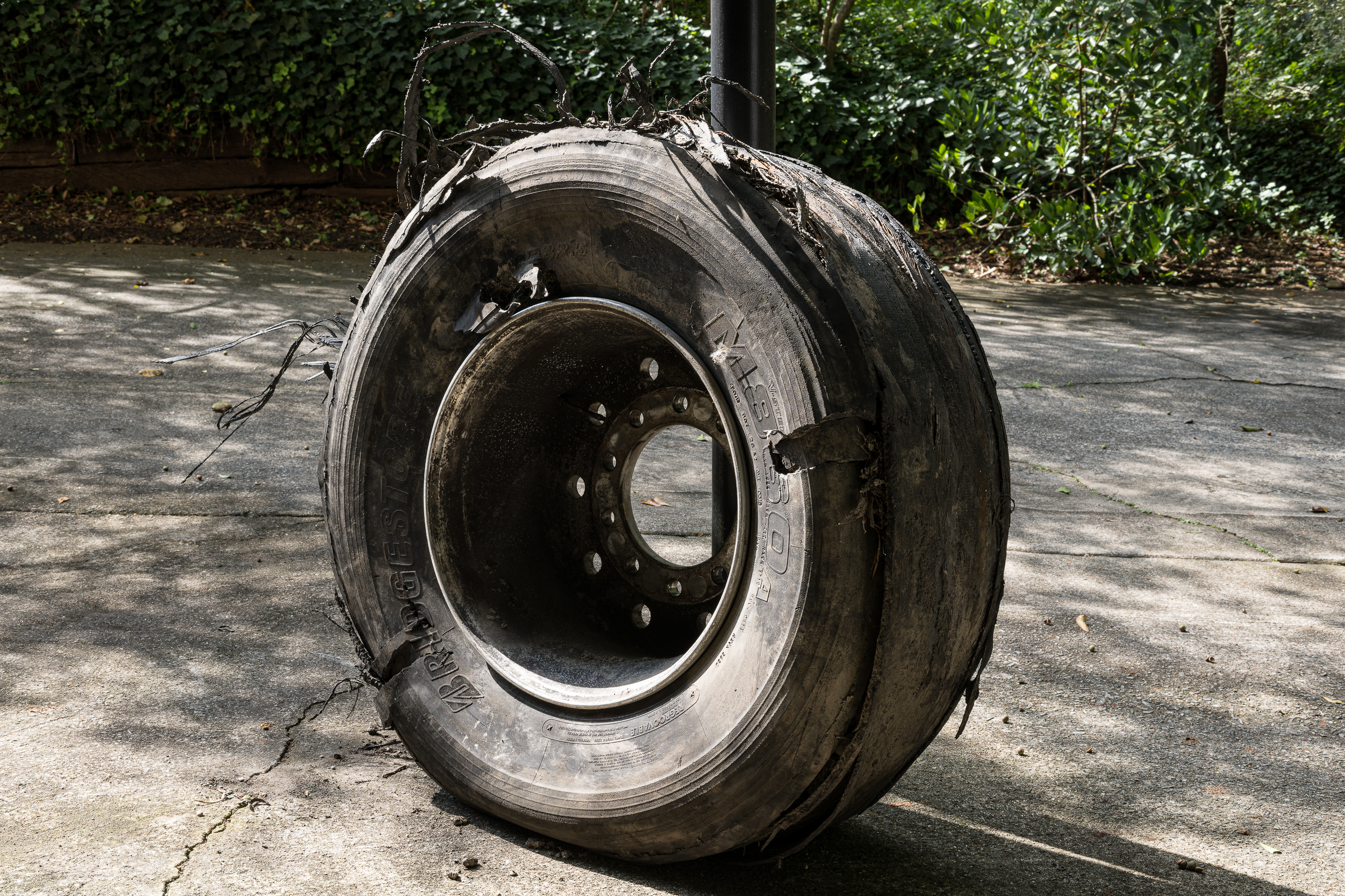
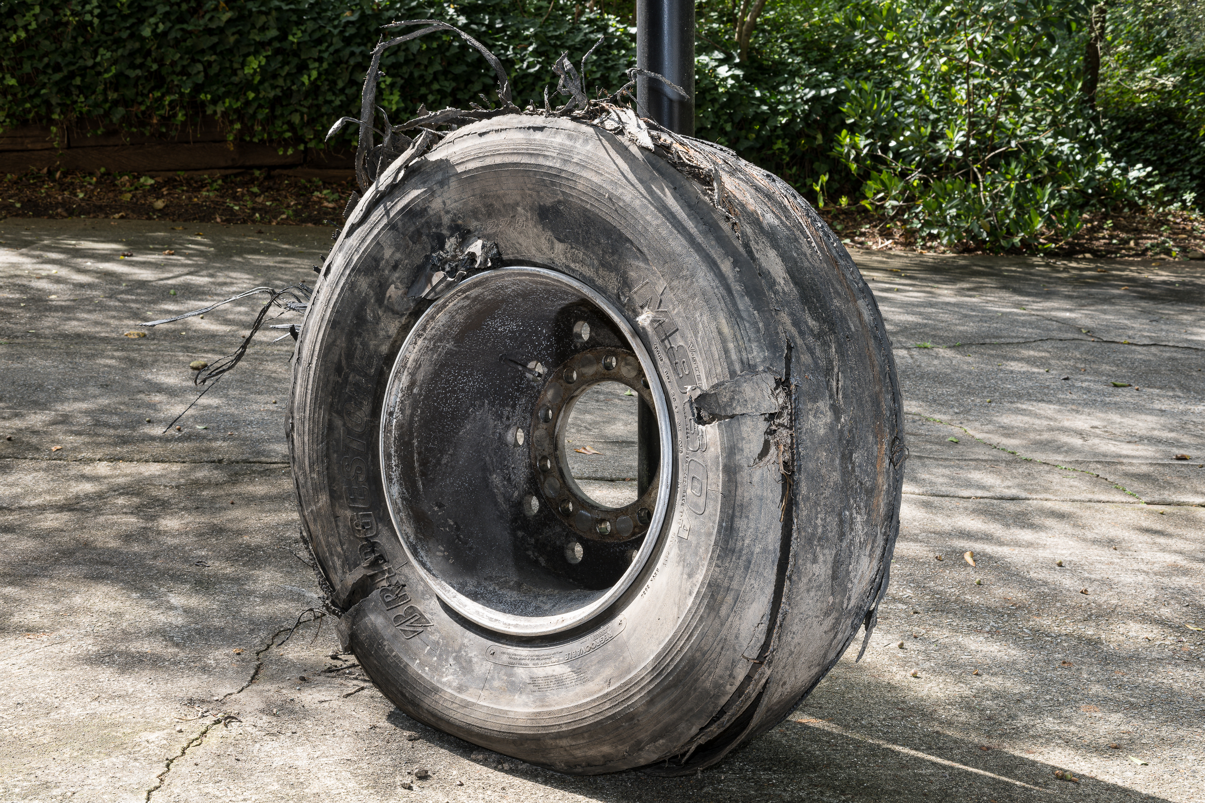
I was driving my old Ford F-150 pickup to retrieve a truck tire and wheel for analysis when I heard a popping then a flopping noise from the rear. I wasn’t sure what it was, so I pulled over and saw the right rear tire had gone flat. [Click on image to enlarge, then click on back arrow to return to this post.]
Made with iPhone 11 Pro Max at f/1.8, 1/120 sec, ISO 32.
I saw this fairly long radial split or cut, but couldn’t tell what had caused it. Being a tire engineer, I regularly inspect my tires while keeping them properly inflated, but I hadn’t noticed any pending issue.
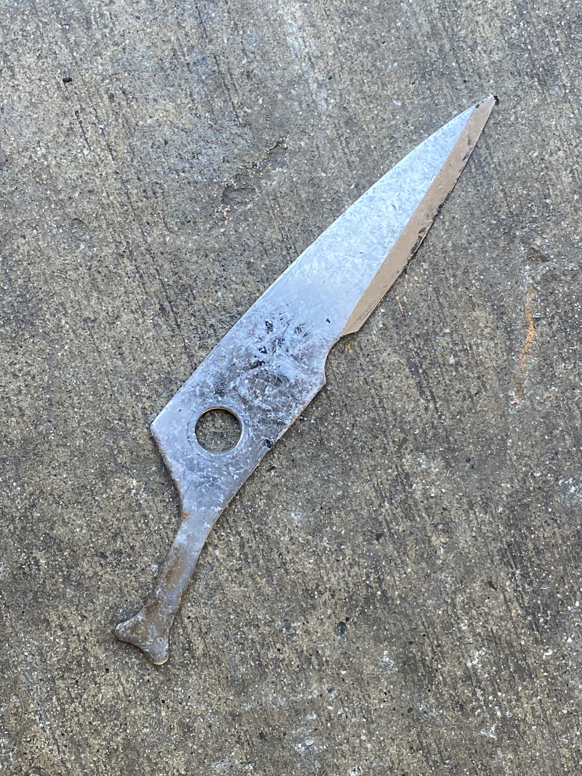
At the tire store, they demounted the tire and called me over to see. Somehow, this blade from a pair of shears cleanly penetrated the sidewall, carcass, and innerliner, and ended up inside the tire. [Click on image to enlarge, then click on back arrow to return to this post.]
Made with iPhone 11 Pro Max at f/1.8, 1/105 sec, ISO 125.
I would never have guessed that this long blade could have so cleanly and completely passed through the sidewall of a tire rotating at 45 mph. And without removing the tire from its rim, I would never have known what caused that radial cut.
Fortunately, in this case I knew the prior condition of the tire and about how suddenly the failure occurred.
In actual cases, it’s extremely rare to have such clean cut evidence (pun intended). In Part Two, I will show several examples of tire conditions that could only have been determined after the tire was demounted.
Takeaways:
-1- While a tire expert can gather information about a failed tire while it is still mounted, a thorough analysis cannot be completed until the tire is demounted from its rim.
-2- Demounting a tire from its rim is essential so the tire beads, the inside of the tire, and the condition of the wheel can all be analyzed. This includes examining for cracks, punctures, mounting/demounting damages, and repairs.
-3- On rare occasions like the one described, the actual cause of the failure is immediately obvious when the tire is demounted.
-4- It is common practice for the first tire expert to receive the tire and wheel assembly to photograph it as mounted, mark the valve position on the outside sidewall (if the beads are still seated), and have the tire professionally demounted. Typically, other tire experts do not need to be present for the demounting.
This tire was photographed in the afternoon on a sunny day. [Click on the image to enlarge. Then click on back arrow to return to this post.]
Mounted tire on wheel outdoors with no flash. (Made with Nikon Z 8 and ZEISS Milvus 50 mm macro on Nikon FTZ II adapter at f/16, 1/10 sec, ISO 64.)
Despite being properly exposed, there are almost no details in the shadows of the tire sidewall or the wheel. Brightening the exposure would have shifted the brightest parts of both the wheel and tire into blown out highlights and all detail there would have been permanently lost. While not essential to the tire or wheel, the brighter spots on the concrete driveway would also have blown out. This would result in a less professional looking image.
Fortunately, the overall exposure itself can remain, and flashes can be used to bring out details in the shadows. [Click on the image to enlarge. Then click on back arrow to return to this post.]
Mounted tire on wheel outdoors with both on-camera flash and second flash at lower right. (Made with Nikon Z 8 and ZEISS Milvus 50 mm macro on Nikon FTZ II adapter. Godox TT685N II in camera hot shoe and Godox AD200 Pro at lower right at f/16, 1/10 sec, ISO 64.)
While keeping the identical exposure, a Godox TT685N II speedlight was slid into the camera’s hot shoe and aimed towards the shadows inside the wheel and on the left side of the tire sidewall. A second Godox flash—an AD200 Pro—was handheld at the lower right, and angled upwards toward the right side where the tread used to be.
These two flashes balanced the natural light and added much-needed detail in the shadows. The result was both a professional appearing image and one where details were not blocked up in dark shadows or blown out in the highlights.
Of course, like almost every photograph I make, both of these images were made with the camera on a tripod. I used a five-second self-timer so I could move over and get the handheld flash at the lower right into position.
Takeaways:
-1- On bright sunny days, there is often too much contrast to capture detail in both the highlights and the shadows.
-2- Increasing the exposure will lighten the shadows, but will cause the highlights to blow out and permanently lose all data and detail there.
-3- Adding one or more flashes to fill in shadows where needed results in more detail in the shadows without losing detail in the highlights.
-4- You may have to make a couple different images with the flashes to get the proper amount of light and the proper angle of light for what you want. When I make more than one image, I only keep the one that shows the details I intended. If you feel you must keep all the images you make, no problem. Only use the best one in reports or as an exhibit.
-5- More good news! The more often you practice with one or more flashes, the more quickly and intuitively you will be able to get both the amount and direction of light that you want.
When inspecting a truck and downloading its HVEDR, it is important to document the actual tire parameters. This includes not only confirming tires sizes, but their load ranges. You must confirm that the tire sizes and load ranges match those on the safety certification label on the door jamb and in the values programmed into the HVEDR.
In its 2023 Truck Tire Data Book, Michelin summarizes the effects of different revs/mile in this Rule of Thumb: “When going from a lower Tire Revs./Mile [sic] to a higher Tire Revs./Mile, the actual vehicle speed is less than the speedometer reading. When going from a higher Tire Revs./Mile to a lower Tire Revs./Mile, the actual vehicle speed is greater than the speedometer reading.”
The revs/mile differences between load ranges in a given tire size might not be large, but they do exist—even in the same line of tires. For example, Michelin lists two 11R22.5 X Multi D tires: one load range G and the other load range H. For the load range G tire, Michelin lists the revs/mile as 496 while it lists 494 revs/mile for the load range H tire. Likewise, for the 11R22.5 Michelin X Line Energy Z tire line, the load range G revs/mile was 502 and the load range H was 503.
So just between two Michelin tire lines, there is a range of revs/mile from 494 to 503 for 11R22.5 tires. Not only that, but for one tire line, revs/mile were higher for the LRH tire than the LRG, while for the other tire line, the opposite was true.
At first it may seem that all tires of the same size would have the same revs/mile. But variations in tire construction, tread design, and tread depth can result in small variations in the actual revs/mile of a specific tire of the same size.
Tire companies determine the revs/mile from the test procedures set out in SAE Recommended Practice J1025. J1025 specifies speed (45 mph), load, inflation pressure, ambient temperature, configuration, break-in, warm up, surfaces, measurement devices, and test distances required for each test.
The four revs/mile values of the four 11R22.5 Michelin tires above weren’t far apart, but it is best to check and confirm. And even though a small difference in revs/mile may not end up being significant in your analysis, you want to confirm that the truck tires sizes and load ranges matched what was used when programming the HVEDR.
Many trucks have a variety of tire brands, sizes, load ranges, or a mixture of original and retreaded tires. In some cases, the truck may be gone or repaired, and all you have to work with is the HVEDR report itself. When you have tire variations or unknown tires, you might consider researching the ranges of any relevant tire property, like revs/mile, then running a sensitivity analysis to quantify the effect that range of values might have on any subsequent analysis involving data from the report.
Takeaways:
-1- During a truck inspection, don’t just document the tire manufacturer(s) and tire size(s), but be sure to include the tire load range(s). Compare their properties with the programmed values in the HVEDR report.
-2- If there are variations in the truck’s tires, check the various tire properties against the HVEDR programmed values.
-3- Using those tire property variations, it might be useful to perform a sensitivity analysis to quantify the effect of a range of revs/mile or other variable.
-4- To learn how to apply HVEDR data, I highly recommend SAE International class C1901 Advanced Applications of Heavy Vehicle EDR Data taught by Wes Grimes, Greg Wilcoxson, Dave Plant, and Brad Higgins: https://www.sae.org/learn/content/c1901/
I needed to document the bolt holes on a wheel that came off the front of a pickup to show whether or not the wheel had been loose on its studs.
After making overall photos of the wheel and tire assembly, I made close-ups of the mounting surface and bolt holes from the back of the wheel. But on the outside of the wheel, the bolt holes were too deeply recessed to use a standard macro lens.
It was important to photograph the lug nut mating surface at the bottom of each recess, but it was nearly impossible both to get light down each recess and to fill the image frame with each hole. I wanted to get sharp, detailed, full frame images of the mating surface—not images cropped from a larger view.
The solution was the unique Laowa Probe lens. (I have previously discussed another unique Laowa super macro lens. I’ve found Laowa lenses to be well made and optically excellent.)
As the photo below shows, the Probe is a 16-inch long tube with a small diameter 24 mm lens surrounded by tiny LED lights at its end. You use a small USB power brick to power those LED lights. Laowa supplies a USB cable with a built-in dimmer switch, but you must supply the power brick. [Click on photo to enlarge, then click on back arrow to return to this post.]
Nikon D850 with Laowa 24mm f/14 2X Macro Probe macro lens made with Nikon Z 7II with Nikon Z 24-70 mm f/2.8 lens and two Profoto B1x studio flashes. f/16, 1/200 sec, ISO 200.
Laowa offers the Probe with several different mounts for many popular DSLR and mirrorless cameras. I used the Nikon F-mount version of the Probe lens on my Nikon D850. Note that all versions of the Probe require manual focusing and exposure; there are no electronic connections between the Probe and any camera.
Fortunately, the lens barrel fit perfectly into the recessed bolt hole, allowing me to get a full frame image of the mounting surface at the bottom. All I had to do was to adjust the intensity of the LEDs, adjust the exposure, and click the shutter. [Click on photo to enlarge, then click on back arrow to return to this post.]
Nikon D850 with Laowa 24mm f/14 2X Macro Probe macro lens made with Nikon Z 7II with Nikon Z 24-70 mm f/2.8 lens and two Profoto B1x studio flashes. f/16, 1/200 sec, ISO 200.
To steady the lens, manually focus, and keep the lens perpendicular to the bottom of the recess, I had the camera mounted on my rolling studio camera stand, which acted like an easily-adjusted tripod on wheels.
As you’ll see, the next two images made with the Probe lens required 0.5 and 0.3 second exposure times, respectively. That range of shutter speeds required that the camera be secured on a tripod to eliminate camera shake. Raising ISO to get handholdable shutter speeds would introduce noise, reduce detail, and reduce dynamic range. That would defeat the whole purpose of using the Probe to get sharp, detailed full frame images.
The first image I made for each paired hole (the wheel was drilled for two bolt patterns) was to show the bolt hole pair, while concentrating on the appropriate bolt hole. [Click on photo to enlarge, then click on back arrow to return to this post.]
Nikon D850 with Laowa 24mm f/14 2X Macro Probe. f/unrecorded, 0.5 sec, ISO 64.
I then slid the end of the Probe deeper into the recess to fill the frame with details of the mounting surface. [Click on photo to enlarge, then click on back arrow to return to this post.]
Nikon D850 with Laowa 24mm f/14 2X Macro Probe. f/unrecorded, 0.3 sec, ISO 64.
I know of no other way to have attained this image without significant cropping and the inherent loss of detail and resolution.
Although it’s not a lens I use all that often, I’ve found the Probe unmatched for photographing inaccessible labels, fasteners, or other components, too. The built-in LED lights around the lens make it a really useful tool.
-1- The Laowa Probe (along with the more recent Peri-Probe) lens is a unique, specialized macro lens that can allow you to photograph areas that are otherwise inaccessible.
-2- The Laowa Probe lens allows you to capture all the resolution and detail of full frame images that would be lost with a significant crop.
-3- If you are stymied about how to photograph a challenging subject, you might be able to find a commercially available specialized solution.
-4- While it is preferable to have specialized lenses at your disposal, you can always rent lenses (or other photography gear) for infrequently encountered situations. Of course, you might find yourself using even seemingly specialized lenses more often if you own them and have them readily available.
Often, evidence is stored in plastic bags or containers with shiny surfaces that result in reflective glare when photographed. This glare can obscure both the content and any markings on the bag or container.
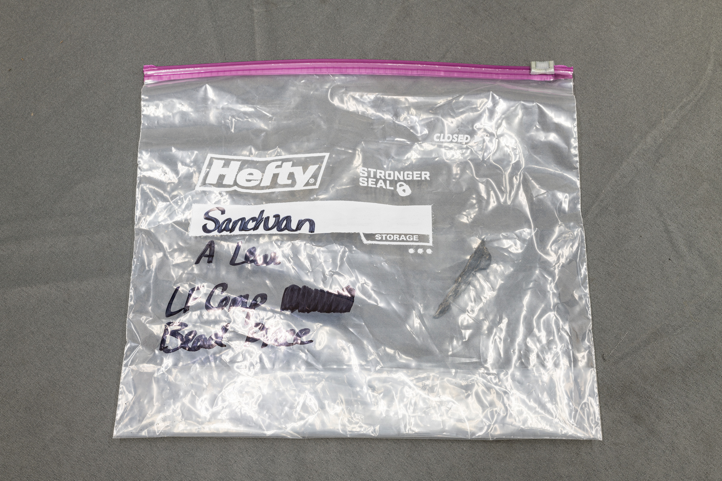
As an example, a small piece of the bead toe from a tire was placed in a plastic bag, which was labeled with a black magic marker. (The writing on the bags in the images below has been intentionally altered to preserve anonymity.)
This first image was made in my Studio Lab using just the overhead LED lights. [Click on image to enlarge, then click on left arrow to return to this post.]
Plastic Evidence Bag without Flashes (Made with ZEISS Milvus 50 mm f/2 Macro lens on Nikon D850 at f/16, 1 sec, ISO 64.)
Even though the image is properly exposed, the overhead LED lights resulted in so much glare that it is difficult to make out the tiny tire piece inside or the writing on the outside of the bag.
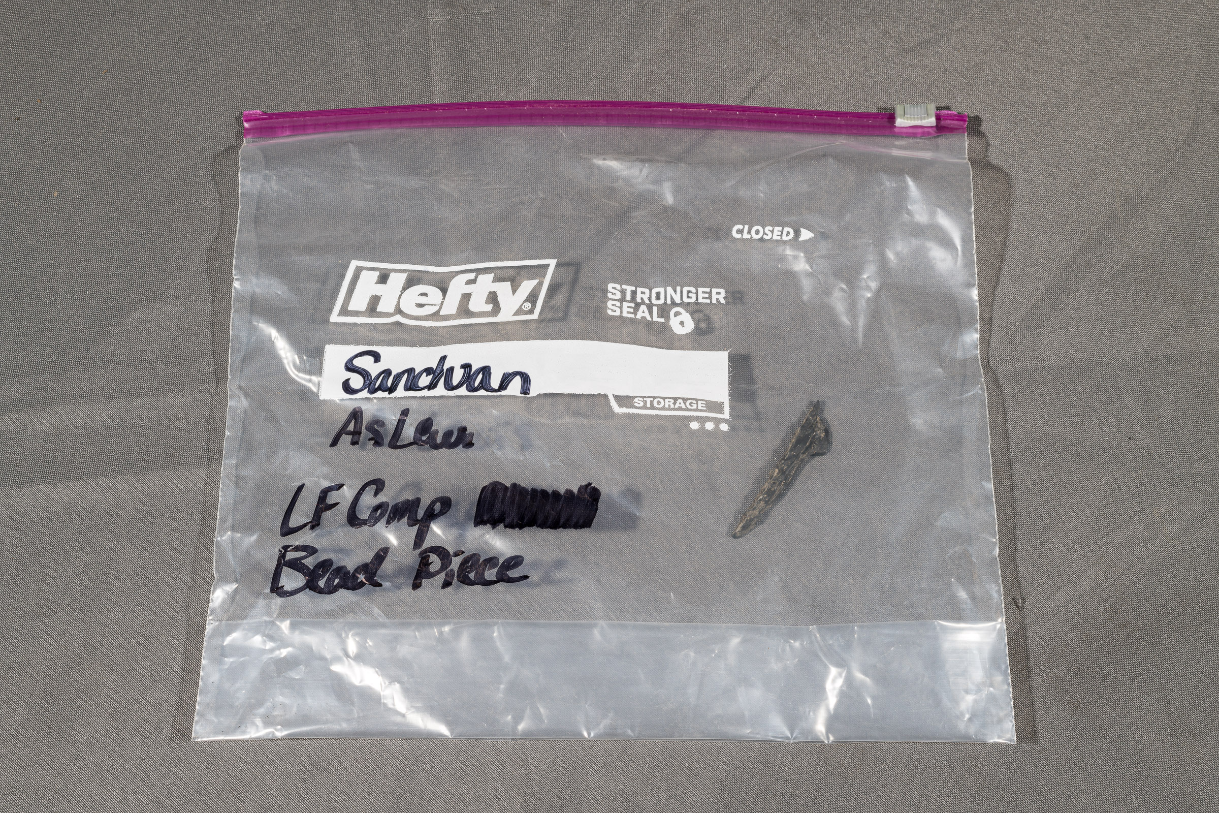
To show both the contents and the writing, I kept the overhead LED lights on, but added a Profoto B1x studio flash on the right and on the left side of the bag. (Note: any remote flashes or speedlights can be used for the same effect.) [Click on image to enlarge, then click on left arrow to return to this post.]
Plastic Evidence Bag with Flashes (Made with ZEISS Milvus 50 mm f/2 Macro lens on Nikon D850 at f/16, 1/200 sec, ISO 64. One Profoto B1x strobe to each side triggered by a Godox TT685N II flash in the camera’s hot shoe.)
Wait, how did adding even more light eliminate the glare? Two things combined to make that work.
First, the added light from the flashes allowed me to significantly reduce the overall exposure. In this case, for both images I kept the aperture at f/16 for depth of field, and the ISO at 64 for lowest noise/highest dynamic range.
In the original image using the overhead LED lights only, the shutter speed was 1 second. When I added the flashes, I reduced the shutter speed down to 1/200 second. This faster shutter speed prevented the overhead LED lights—and their reflections—from recording at all. If I turned off the flashes, the image would have been black, even though the overhead LED lights were on.
Second, the light that reflected from each flash bounced away from its respective flash, and not into the camera lens. Hence, their reflections were not recorded by the camera.
Takeaways:
-1- To reduce or eliminate glare from overhead lights, reduce the exposure enough to cause the image to go black, or nearly so.
-2- Add one or more flashes positioned (usually to the sides) such that any reflections bounce away from the lens, not into it.
-3- Adjust the power of the flash(es) to properly light the subject at the new exposure.
-4- Note: With curved or irregularly shaped objects (like plastic bags), some localized reflections may remain. These may or may not be moved or eliminated by changing the positions of the camera or the flash(es).
When your subject has multiple similar features, you’ll need to mark each of them to distinguish among them in your photographs. These markings must be repeated on the other side of your subject, too, if applicable.
Since you are dealing with evidence, you should never make permanent marks unless agreed to by all parties involved beforehand. Instead, it’s best to use removable stickers or labels.
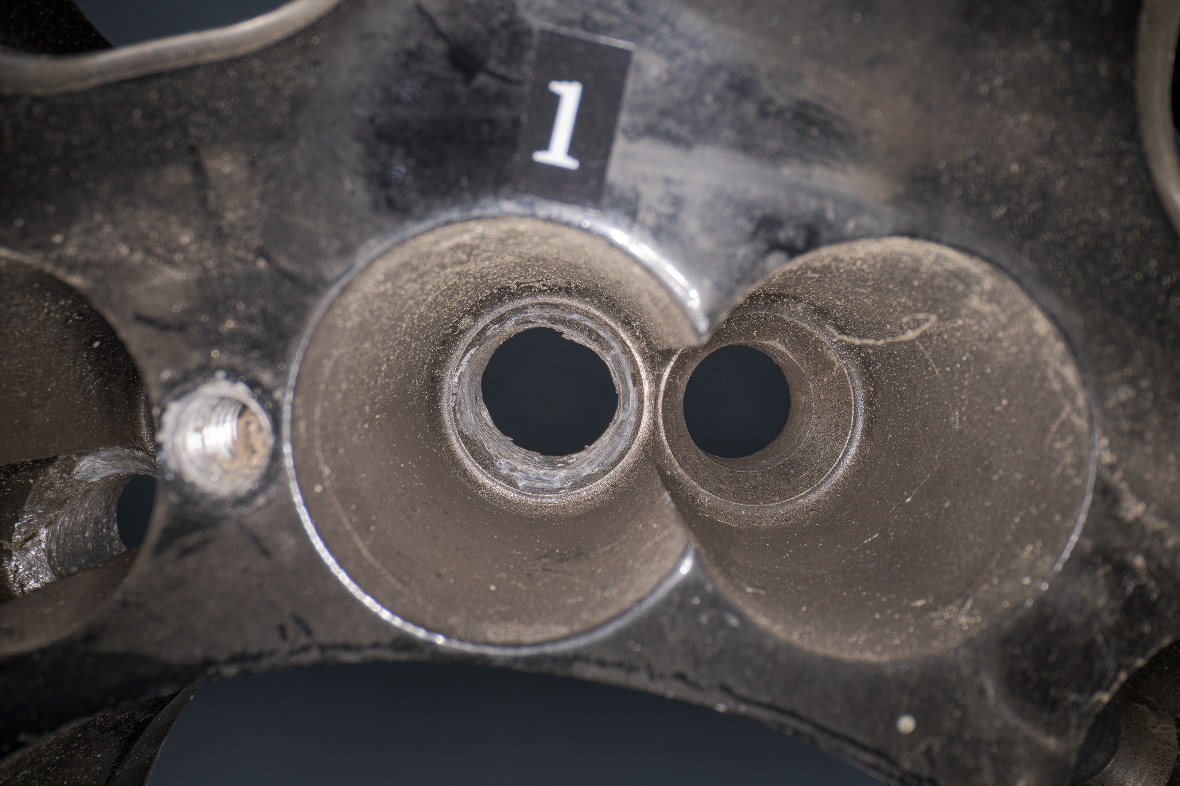
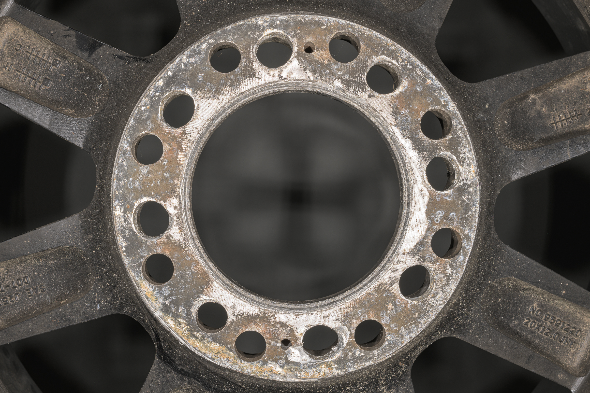
Before applying any labels, photograph the subject as you received it. This will ensure no part of the evidence is masked. As an example, here is a photograph of the mounting surface of an eight-bolt wheel with sixteen holes so it can be used with more than one bolt circle. (Click on image to enlarge, then click on the back arrow to return to this post.)
Nikon D850 with ZEISS Milvus 50 mm macro lens and Nikon R1C1 macro flashes. f/16, 1/200 sec, ISO 64.
Using a Brother P-touch labeler, I made one long label with two strings of numbers from 1 through 8, then cut between each number to create small labels of each individual number. The goal was to make the labels as small—yet as legible—as possible so they would mask the least amount of the evidence.
Choose a font with legible numbers, and set the font style to bold. Depending on the color of evidence, I usually use either white on black or black on white labels. On rare occasions, I have used black on clear labels. It’s advantageous to have all three label tapes available.
A label maker creates labels that are more legible and more professional looking than writing numbers by hand on torn pieces of tape.
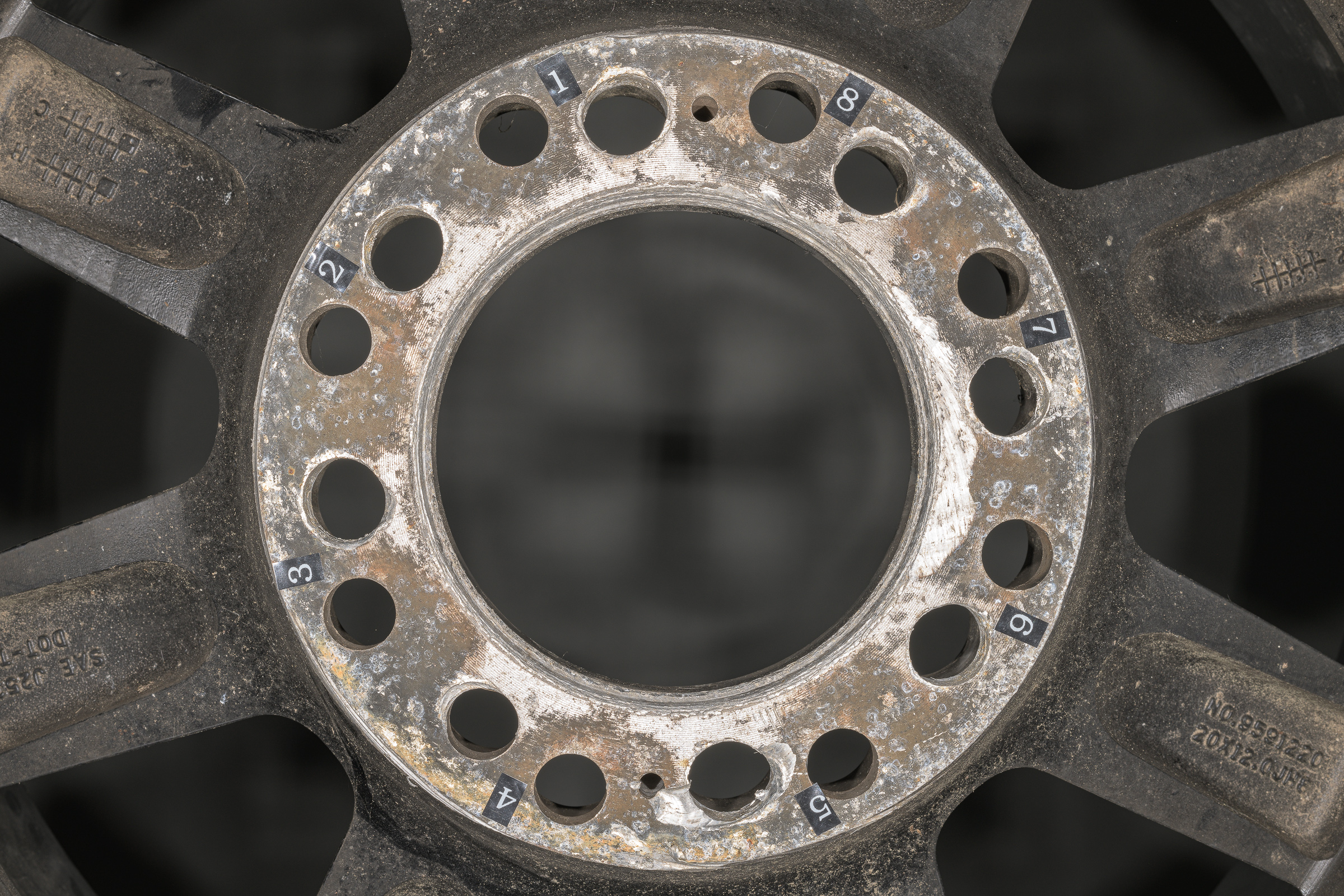
For this wheel, I numbered the holes in pairs. Note that the numbers are counterclockwise on the inside so they will correspond with the same numbers on the outside of the wheel, which were clockwise. (Click on image to enlarge, then click on the back arrow to return to this post.)
Nikon D850 with ZEISS Milvus 50 mm macro lens and Nikon R1C1 macro flashes. f/16, 1/200 sec, ISO 64.
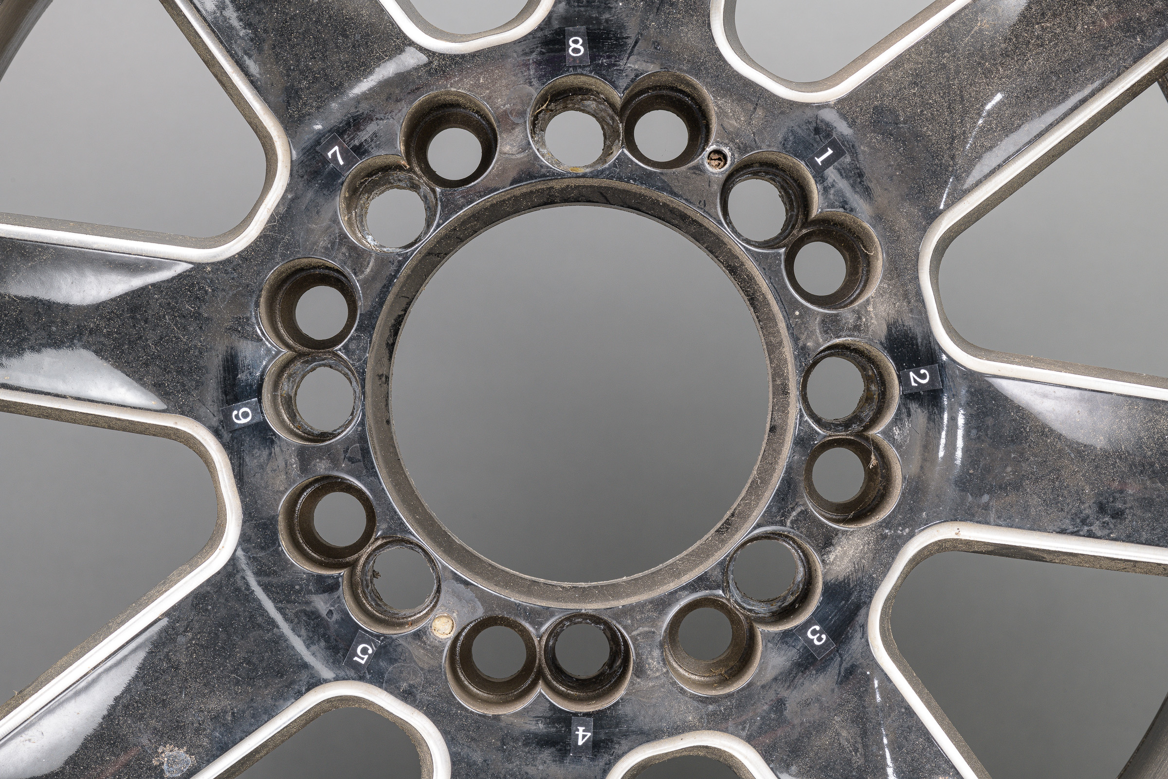
Here is the outside of the wheel showing the clockwise bolt hole pair labels. (Click on image to enlarge, then click on the back arrow to return to this post.)
Nikon D850 with ZEISS Milvus 50 mm macro lens with two Profoto B1x in diffused silver umbrellas. f/16, 1/200 sec, ISO 64.
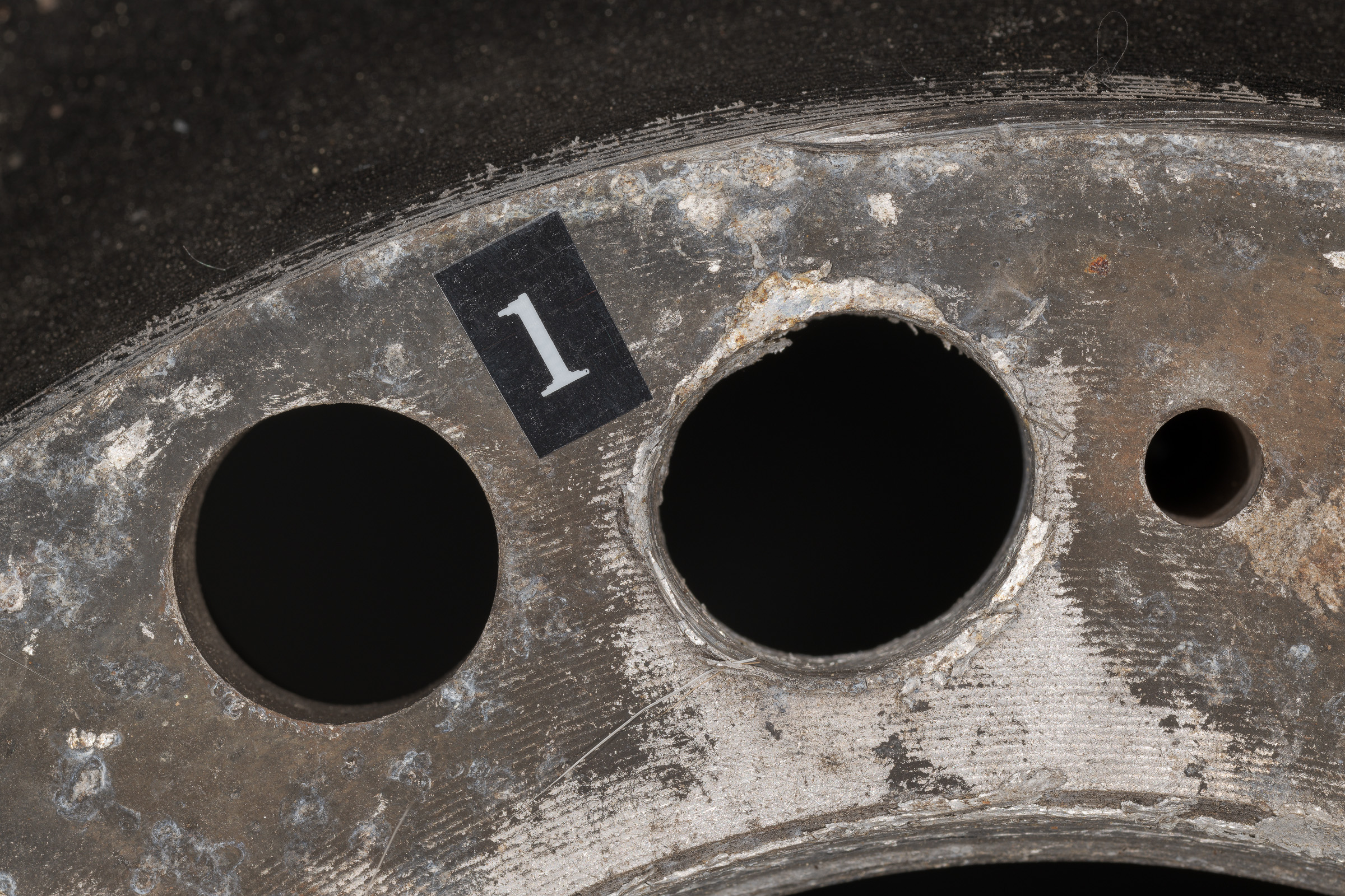
Now close-ups of every hole will be easily identified whether on the inside…
Nikon D850 with ZEISS Milvus 100 mm macro lens and Nikon R1C1 macro flashes. f/16, 1/200 sec, ISO 64.
…or the outside of the wheel. Note that the labels are a good size in the close-ups without overwhelming the subject. Also note that the label is still effective even if it is out of the depth of field of the subject and is slightly out of focus.
Nikon D850 with Laowa 24mm f/14 2X Macro Probe. f/unrecorded, 0.5 sec, ISO 64.
Takeaways:
-1- After photographing evidence as found or received, mark repetitive features on any sides that will be photographed.
-2- Do not make permanent marks on evidence.
-3- Mark evidence with small, legible, and removable labels instead of handwritten numbers on torn pieces of tape.
-4- While labels should be included in close-ups, they do not have to be within the depth of field of the subject as long as they are still discernible.
-5- After making each close-up image with its label, you may want to remove the label and take another photograph without it. Having your camera on a tripod will allow you to made identical shots both with and without the label.
It is essential to keep truck tires properly inflated so they can carry the load, wear evenly, maximize fuel mileage, and maintain their integrity. Chronic overdeflection (overinflation, underinflation, or a combination) is a common cause or contributor to tire failures.
During pre-trip inspections, the Federal Motor Carrier Safety Regulations (49 CFR §396.13) requires the driver “be satisfied that the motor vehicle is in safe operating condition.” This includes the truck’s tires . As part of that pre-trip tire inspection, a driver is trained to look for low or flat tires. But there is no requirement that the driver check the air pressure with a gauge. In fact, while going through truck driving school before getting my CDL, we never once used an air pressure gauge during our pre-trip inspection lessons, daily routines, or exams.
It would be an onerous task to require a driver to check the air pressure of all eighteen tires on a typical tractor trailer before every trip. As an alternative to a gauge, some drivers use a “tire thumper” (usually a rubber mallet or some kind of a bat) to check their tires. If a tire is inflated, the thumper would bounce right off. Striking a tire with little or no air would have no bounce back, but would respond with a flat thud. While a thumper can’t determine if a tire is properly inflated, it can let you know if a tire is flat or near flat. [Click on image to enlarge, then click back arrow to return to this post.]
Only the bottom four of these will give you an accurate truck tire inflation pressure. (Made with ZEISS Milvus 50 mm f/2 Macro lens on Nikon D850 at f/16, 1/200 sec, ISO 64. Used one Profoto B1x studio strobe with silver umbrella with diffuser on each side.)
Back in 1998, I bought the Trucker’s Toothpick & Tire Tester at the top of the photo at a truck stop just for fun. (Both the name of the product and the company are rather whimsical.) It is a weighted metal stick with a hand grip on one end and a protective cover on the other. Along with various wooden bats, it is typical of tire thumpers sold commercially. While their benefits are minimal, at least thumpers prevent a driver from starting off on a trip with a flat tire.
The three stick gauges in the middle of the photo look similar, but their dual heads are at different angles. One of them is bound to fit when the metal valve stems of either the inner or outer tire of a dual pair are bent and otherwise inaccessible. They prevent you from bleeding air out of the tire as you try to get the gauge head to seat on the valve.
Stick gauges seem tricky to read until you understand how their scale works. I’ll describe that below.
The digital pressure gauge at the bottom is the easiest to read (and photograph, if you do that—I don’t).
Here’s how to read a truck tire stick gauge. Assume you’ve just checked the air pressure of a steer axle tire and got the reading below. [Click on image to enlarge, then click back arrow to return to this post.]
Scale on truck tire inflation pressure gauge. (Made with Nikon 105 mm Micro lens on Nikon D850 at f/16, 1/200 sec, ISO 64. Used one Profoto B1x studio strobe with silver umbrella with diffuser on each side.)
At first glance, the scale might not seem to make sense with the decimals between the longest hash marks. (Gauges typically start at 10 psi, not 0 psi; anything less than 10 psi is obviously flat.)
Zooming in might help make deciphering the scale more clear. (This photo has been rotated clockwise to be oriented as you would read the scale in use.) [Click on image to enlarge, then click back arrow to return to this post.]
Rotated close-up of scale on truck tire inflation pressure gauge.(Made with Nikon 105 mm Micro lens on Nikon D850 at f/16, 1/200 sec, ISO 64. Used one Profoto B1x studio strobe with silver umbrella with diffuser on each side.)
Let’s start with the 100 psi mark. (Note that on this gauge, the 100 psi hash mark happens to intersect the second zero.) The next short hash mark down represents 102 psi. One shorter hash mark down is 104 psi. Just below that, the longer hash mark near the center of the scale represents 105 psi. The next short hash mark at the right edge below that is 106 psi. Below that, the short hash mark is 108 psi. Next is the longer hash mark for 110 psi. Using this information, you can see the inflation pressure reading above was 118 psi.
To summarize, all the hash marks along the right edge of the scale are in 2 psi increments. Half way between the decimals, the longer hash marks near the center of the scale are in 5 psi increments.
Anywhere along the scale, anytime the end of the barrel is halfway between two consecutive short hash marks, the inflation pressure is 1 psi greater than the short hash mark above it.
Takeaways:
-1- While truck tires must be properly inflated, the Federal Motor Carrier Safety Regulations do not require truck drivers to check tire inflation pressures with a gauge during their pre-trip inspections.
-2- Tire thumpers can indicate if a tire is flat or almost flat, but cannot determine the inflation pressure.
-3- Different angles of dual head inflation pressure gauges can help access bent valve stems.
-4- If using a stick gauge, make sure you accurately read the scale.
In an earlier post, I showed how shooting a sponge with a side flash gave depth to its surface that couldn’t be shown using a direct flash. I used a sponge since sponges are small, readily available, and easy to practice with anywhere. In this post, I’ll show how a side flash gives depth to an automotive subject—namely, a tire tread.
For this first image, I didn’t use any flash, but adjusted the camera for a proper exposure for the ambient light. It’s properly exposed, but the depth and extent of the cuts and chips out of the tread aren’t apparent. (Click on photo to enlarge, then click on back arrow to return to this post.)
Perpendicular to tread with no flash. (Made with ZEISS Milvus 50 mm f/2 Macro lens on Nikon D850 at f/16, 4.0 sec, ISO 100.)
This photo was made in my Studio Lab, which has so many LED shop lights overhead people say it looks like an operating room. Even though the room looks bright to our eyes, there is not as much ambient light for photography as you might think. In fact, to make the image above required a 4.0 second shutter speed, which obviously precluded handholding the camera. (I also increased the ISO 2/3 stop from 64 to 100.)
For the second shot, I added a Profoto B1x flash to each side, almost perpendicular to the camera, shooting across the tread. I triggered them with a Nikon SB-910 flash in the hotshoe that was pointed straight up at a very low power so it would not contribute to the exposure. (Click on photo to enlarge, then click on back arrow to return to this post.)
Perpendicular to tread with one flash to each side. (Made with ZEISS Milvus 50 mm f/2 Macro lens on Nikon D850 at f/16, 1/200 sec, ISO 64. One Profoto B1x strobe to each side triggered by a Nikon SB-910 flash in the camera’s hot shoe.)
Side flash enhances texture by creating shadows. Diffused ambient light and direct flash lighting both evenly light your subject, which fills in the shadows, which, in turn, reduces the appearance of any textures.
[Technical aside #1: With cross-light from the added side flashes, the shutter speed was 9 2/3 stops faster at 1/200 second and the ISO was 2/3 stop less at 64, for a total of 10 1/3 stops less light than the first shot. If the flashes were turned off for the second photo, that exposure would have resulted in a pure black image. The flashes were adjusted to give the proper amount of light for the exposure. This is called a full flash image, where all of the light is provided by flash. This differs from a fill flash image where the light from any flash enhances the ambient exposure, but flash isn’t the only light source. More on this later.]
[Technical aside #2: For an equivalent ambient light image, instead of a 4.0 second shutter speed and ISO 100, you could use 1/60 second shutter speed and ISO 256,000. The 1/60 second shutter speed may allow you to handhold the camera, but ISO 256,000 is guaranteed to be extremely noisy and noticeably lacking in dynamic range. Not a good alternative at all.]
Four major takeaways:
-1- As with the earlier sponge example, flash light coming from the side brings out texture by creating shadows.
-2- Both diffused ambient light and direct flash lighting flood every surface with the same light, obscuring texture and depth differences.
-3- Indoor ambient light may look bright to our eyes, but it will require very long exposures or an extremely high (and noisy) ISO to make the photograph.
-4- You must adjust your exposure accordingly when going between ambient light and full flash lighted images.